CASSIOPE SPACECRAFT (Swarm-E)
PROCESSED DATA HANDBOOK
Coordinate Systems
The CASSIOPE spacecraft body frame axes are defined as follows:
- +X points through RRI
- +Y points in the direction of the SEI boom
- +Z points out the bottom of the spacecraft
For the purpose of attitude determination, a “Common Reference Frame” (CRF) is defined that is oriented very close to that of the spacecraft body frame, but represents the midpoint of the star tracker attitude solutions (the two star tracker solutions diverge from each other very slightly due to thermal and other aberrations).
CRFx ≈ Bodyx
CRFy ≈ Bodyy
CRFz ≈ Bodyz
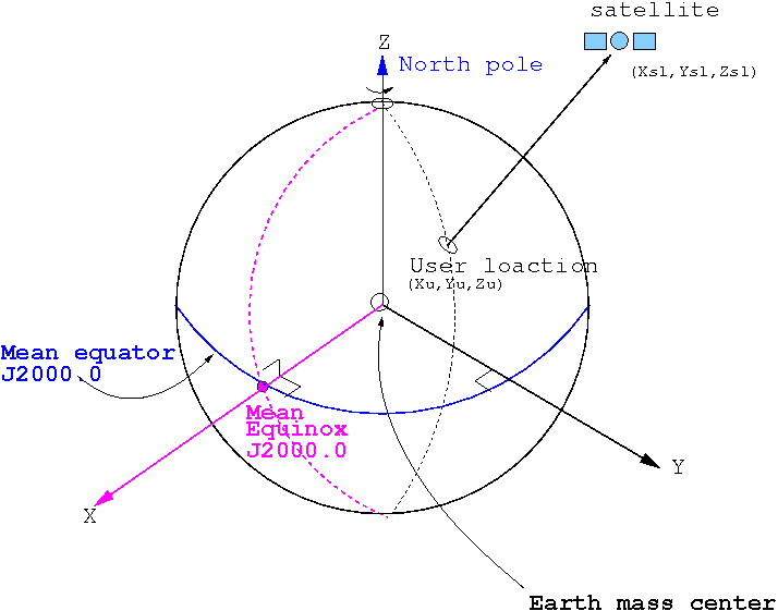
Inertial Coordinates
Inertial Coordinates used in the CASSIOPE products are in the ICRF J2000 reference frame. As per the European Space Agency Reference System and Frames:
This is a quasi-inertial reference system (footnotes 1) . It has its origin at the earth’s centre of mass. X-axis points in the direction of the mean equinox at J2000.0 epoch, Z-axis is orthogonal to the plane defined by the mean equator at J2000.0 epoch (fundamental plane) and Y-axis is orthogonal to the former ones, so the system is directly (right handed) oriented. The practical implementation is called (conventional) Celestial Reference Frame (CRF) (footnotes 2) and it is determined from a set of precise coordinates of extragalactic radio sources (i.e., it is fixed with respect to distant objects of the universe). The mean equator and equinox J2000.0 were defined by International Astronomical Union (IAU) agreements in 1976, with 1980 nutation series (Seildelmann, 1982 and Kaplan, 1981), which are valid analytic expressions for long time intervals (the former reference epoch was 1950.0).
Notes:
- It is not an inertial system in a strict way, because it is affected by the accelerated motion of the earth around the sun (annual revolution).
- Notice that Reference System and Reference Frame are different concepts. The first one is understood as “a theoretical definition”, including models and standards for its implementation. The second one is its “practical implementation” through observations and a set of reference coordinates (set of fundamental stars –for a Celestial Reference Frame– or fiducial stations –for a Terrestrial Reference Frame–).
- For consistency with legacy products J2K is treated as equivalent to ICRS with error in the hundredths of an arcsecond.
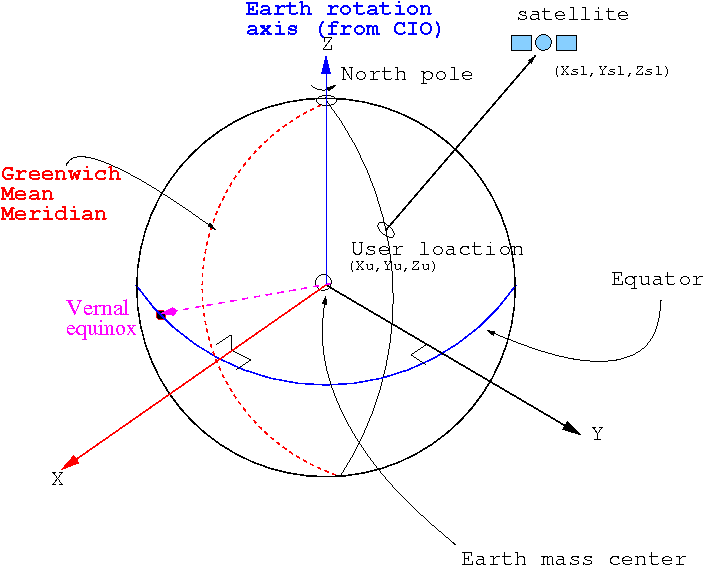
Geographic Coordinates
CASSIOPE products use the International Terrestrial Reference Frame (ITRF) for Cartesian Geographic Coordinates (GEO), and the WGS-84 system for latitude, longitude, and altitude values. As per the European Space Agency Reference System and Frames:
This is a reference system co-rotating with the earth in its diurnal rotation, also called Earth-Centred, Earth-Fixed (ECEF). Its definition involves a mathematical model for a physical earth in which point positions are expressed and have small temporal variations due to geophysical effects (plate motion, earth tides, etc.). The TRS has its origin in the earth’s centre of mass. Z-axis is identical to the direction of the earth’s rotation axis defined by the Conventional Terrestrial Pole (CTP), X-axis is defined as the intersection of the orthogonal plane to Z-axis (fundamental plane) and Greenwich mean meridian, and Y-axis is orthogonal to both of them, making the system directly oriented. The realization of this system is named (conventional) Terrestrial Reference Frame (TRF) and it is carried out through the coordinates of a set of points on the earth serving as reference points (footnotes 1). An example of TRF is the International Terrestrial Reference Frame (ITRF) introduced by the International Earth Rotation and Reference Systems Service (IERS), which is updated every year (ITRF98, ITRF99, etc.). Other terrestrial reference frames are the World Geodetic System 84 (WGS-84), which is applied for GPS, the Parametry Zemli 1990 (Parameters of the Earth 1990) (PZ-90) for GLONASS, or the Galileo Terrestrial Reference Frame (GTRF) for Galileo system.
Notes:
- A conventional TRF is defined as a set of physical points with precisely determined coordinates in a specific coordinate system that is the realization of an ideal TRS [Boucher and Altamimi, 2001].
- For consistency with legacy products ITRF is equal to geographic coordinates by definition at above the earth’s surface.
Magnetic Coordinates
Magnetic coordinates for Cassiope products are calculated using the International Geomagnetic Reference Frame (IGRF) model.
Magnetic Local Time (MLT) is the magnetic longitude measured in hours (1 hour = 15 degrees), with the zero point fixed relative to the Sun such that MLT=12 is facing the sun. MLT is calculated as:
MLT = (Magnetic_Longitude – Subsolar_Magnetic_Longitude + 180)/15 where the longitudes are in degrees and the MLT is in hours.
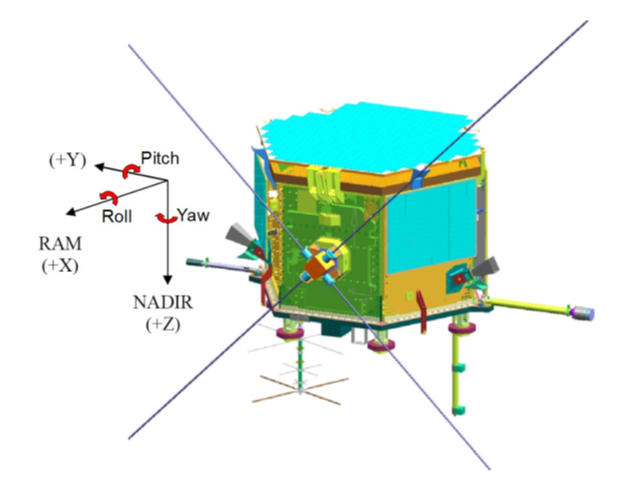
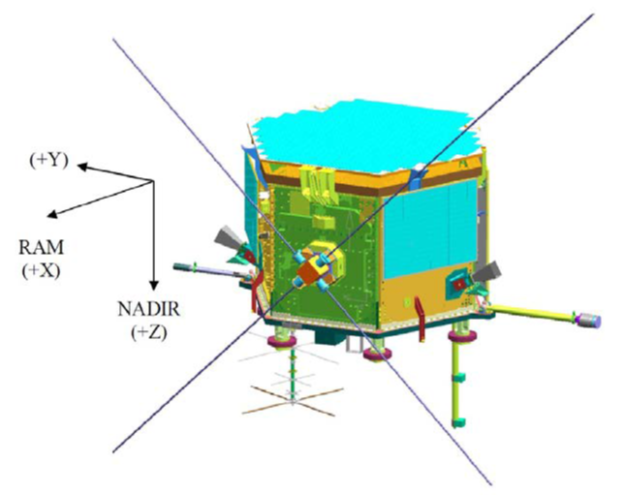
Orbital Reference Frame
Spacecraft attitude is defined by the angles of yaw, pitch, and roll relative to the “Nadir” pointing direction. Nadir is defined as:
- S/C +Z along the negative position vector, R
- S/C +Y is along the negative orbit normal (-R x V = Z x V)
- S/C +X is toward velocity (X = Y x Z)
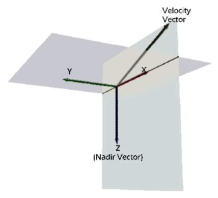
- Roll is the rotation of the S/C about the X axis (positive is from +Y towards +Z).
- Pitch is the rotation of the S/C about the Y axis (positive is from +Z towards +X).
- Yaw is the rotation of the S/C about the Z axis (positive is from +X towards +Y).
The attitude of the satellite is determined by rotating from the “Nadir” attitude in the order roll, pitch, yaw (the so-called 321 order), keyed on the ICRF, not the published ITRF.